Hi again Onioneers,
As you know our team is always busy making updates and improvements to your Omega and have just released a new feature; the Omega2 can now generate hardware-based PWM signals! We’ve worked to enable the on-board hardware PWM units and you can now generate timing-accurate signals on both GPI0 18 and GPI0 19.

We’ve outlined the steps including updating your Omega, generating PWM signals from the command line and a quick review of some practical applications that require timing accurate PWM signals.
Updating your Omega
A quick and easy Omega firmware update is required for this feature.
Connect to your Omega’s command line, make sure you’re connected to the internet, and run:
oupgrade --latest
This will take a few minutes. When it’s done, we’ll move on to the fun part.
This feature is supported in Omega firmware builds 195 and up.
Generating PWM Signals
If you’re a little foggy on what Pulse Width Modulated (PWM) signals are all about and need a refresher, take a look at our recent PWM quick-start article.
With the latest firmware installed, the Omega is ready to make use of the hardware PWM units built into the SoC to generate PWM signals. This is facilitated through the Linux sysfs interface. There’s many great resources available online about the sysfs interface, take a look at this kernel documentation article for a good starting point.
Enabling the PWM Pins
As you may be aware, the Omega’s pins are multiplexed allowing you to use a small number of pins for many different functions. As an example, the pin that normally corresponds to GPIO18 can be configured to instead act as PWM channel 0. And GPIO19 can be configured to act as PWM Channel 1.
* PWM Channel 0 = GPIO18
* PWM Channel 1 = GPIO19
It’s very easy to make changes to the pin multiplexing configuration as it can be done straight from the command line.
Here we need to switch the GPIOs to PWM, this can be done by just running the following commands:
For GPIO18: omega2-ctrl gpiomux set pwm0 pwm
For GPIO19: omega2-ctrl gpiomux set pwm1 pwm
This multiplexing configuration will need to be repeated after each reboot of the Omega.
Actually Generating the Signals
Now we are ready to generate the PWM signals by using the following command:
onion pwm <CHANNEL> <DUTY CYCLE> <FREQUENCY>
Where:
CHANNELis either0(GPIO18) or1(GPIO19)DUTY CYCLEis the percentage of time the signal is ‘on’, expressed 0 – 100FREQUENCYis the signal frequency, expressed in Hz
Stopping the PWM Signal
It’s also possible to completely stop the PWM signal:
onion pwm <CHANNEL> disable
Dimming an LED
For example, the Omega’s PWM signals can be directly connected to an LED and, instead of just turning it on or off, we can make it varying degrees of dim.
To start, let’s enable PWM Channel 0 on GPIO18:
omega2-ctrl gpiomux set pwm0 pwmIn this example we will create a PWM signal on GPIO18 with a 40% duty cycle (signal is high 40% of the time, low 60% of the time) at a frequency of 60Hz, and so:
onion pwm 0 40 60
Then disable to the PWM signal:
onion pwm <CHANNEL> disable
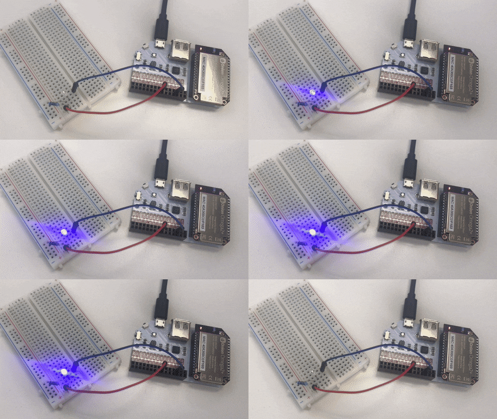
Here is how an LED looks going from 20% duty cycle to 40%, to 80%, and then off:

Controlling a Servo
Now that the Omega is capable of generating hardware-based, timing accurate PWM signals, you can also connect a servo directly to the Omega.
Again, you’ll have to first enable the PWM channel:
omega2-ctrl gpiomux set pwm1 pwmThen the servo can be controlled from the command line:
onion pwm 1 5.5 60

You will just have to do some calculations regarding PWM signal pulse-width to servo angle.
Happy hacking! Make sure to let us know what awesome PWM-powered stuff you make!
